Installation Instructions - SEN/H/R3 Sentry three channel 'code hopping' 433Mhz remote control system
Compatibility
Suitable for
use with all remote controlled garage door operators having an external
receiver connected with three terminals
Electrical
Connections
Connections
to the receiver are by screw terminals, connections are as follows
:-
Power : connect to a 12 to 24 volt AC or DC power source
(this is available from most makes of garage door operator)
Important :-
On multiple door installations take power from one motor only
Relay outputs
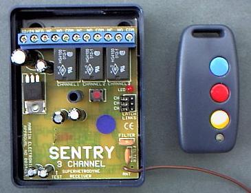
channel 1 = Yellow button on fob
channel 2 = Red button on fob
channel 3 = Blue button on fob
(three individual outputs)
Relay
connections
NC - 'volt free' relay contact - normally closed
NO - 'volt free' relay contact - normally open
COM - relay contact 'common'
Note :- for normal garage door or gate applications simply connect a length of
'bell wire' from the 'COM & 'NO' terminals to the
pushbutton connections of the garage door operator
Position the brown aerial wire away from other wiring or metalwork
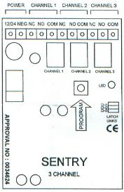 |
Mode of operation Each channel can be configured in one of two modes :- momentary mode - each relay is energized when the corresponding keyfob button is pressed and releases when the button is released. (use momentary mode for garage door & gate control) latch mode - the relay is switched on when the keyfob button is pressed and remains on until the button is pressed again. - select this mode by connecting the jumper plugs to pins on the P.C.B. (3x jumper plugs supplied) |
The receiver unit should be mounted in a position away from metal obstructions and as high as is practical. In most cases range will be increased by mounting the receiver with the brown aerial wire hanging downwards. The receiver unit can be screwed into position or mounted with self-adhesive Velcro pads.
433.920Mhz MPT 1340 UK approved frequency
![]()
![]()
433Mhz
three channel 'code hopping' radio control system
Stock No. SEN/H/R3
Amourelle Products, Unit 16 James Scott Rd, Halesowen, West Midlands B63 2QT www.Garage-Door-Remotes.co.uk
Sentry 433Mhz rolling code
system
Digital code
system
The keyfob
transmitters communicate to the receiver by digitally coded
transmission. Each transmitter is factory
pre-programmed with a unique set of security codes from a choice of 260
million different codes and 'hops' to a new code after every
operation, the receiver unit can learn & memorize the unique
security code signature of up to eight individual keyfob transmitters.
Your receiver will be pre-programmed ready for use with any keyfobs purchased with it, but will require programming if any further keyfobs are added.
Programming
instructions
1. Remove the receiver cover and locate the small red 'Program'
button
on the printed circuit board and press it briefly, the LED next to the
button will flash once to indicate that the receiver has entered into
'code learning mode' (the 24v power must be connected)
2. Hold the new
keyfob transmitter two metres away from the receiver and press
and hold
any button until the receiver LED has flashed three times.
3. Repeat steps 1. & 2. above to program a total of up to eight
keyfobs.
4. Exit
programming mode by repeatedly pressing the red
'program' button until the receiver LED illuminates for
one second, your keyfob(s) should now operate your receiver.
Clearing the memory - (necessary if a handset has been lost or
stolen)
Repeat steps 1 & 2 above eight times (using each of your keyfobs) to
'over write' all eight memory
slots, this will ensure any previously memorised fobs will be erase
SEN/H/T3 keyfob
keyfob
Battery Replacement
Remove
the fixing screw on the back cover
and open the keyfob casing to reveal a 12 volt car
alarm battery type LR23A